Blog
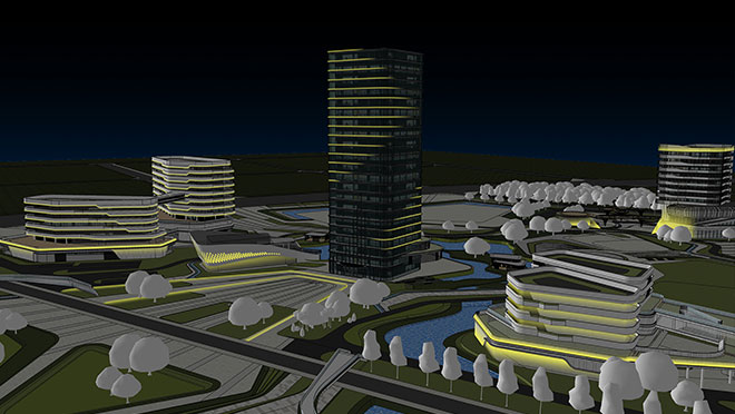
Dynamic Façade Lighting – 11 Technical Highlights on DMX512 RGB Neon Strip Applications
Dynamic Façade Lighting – 11 Technical Highlights on DMX512 RGB Neon Strip Applications
Ryan Lee.UpdatedJuly 4, 2025|9 mins Read
Overview:
This article primarily introduces key technical points for applying RGB neon strip lights controlled by the DMX512 protocol in dynamic architectural façade lighting projects. It covers critical aspects, including product technology, installation, wiring, and control systems, to help establish a foundational understanding of practical DMX512 applications.
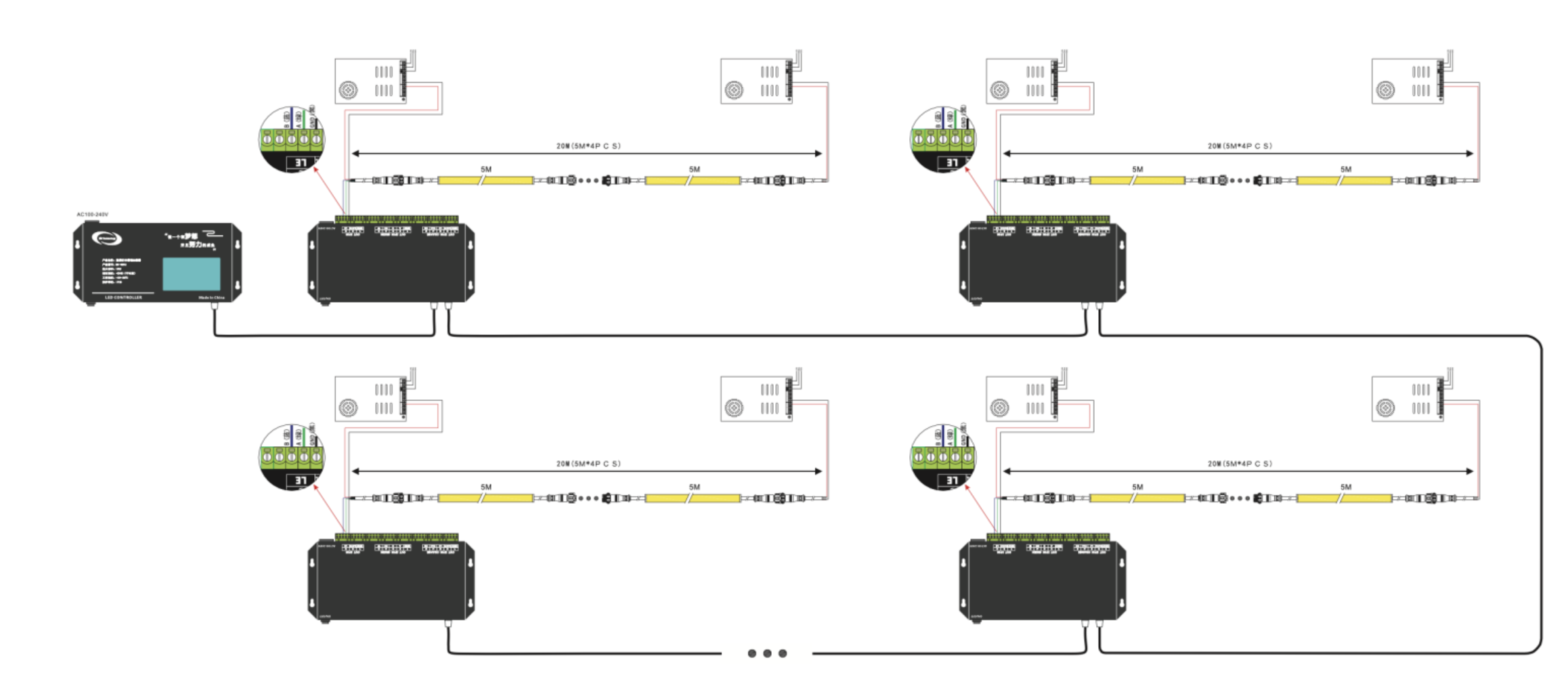
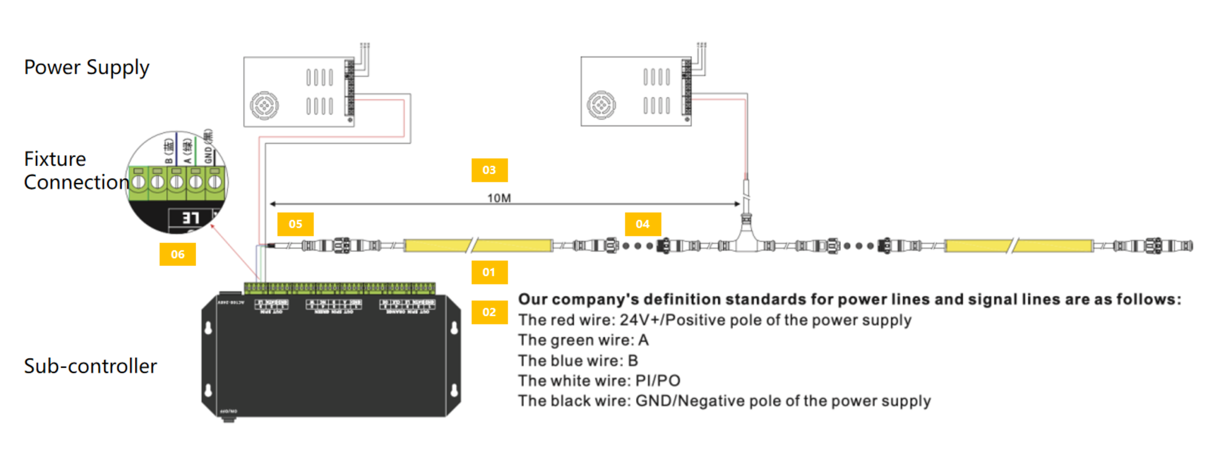
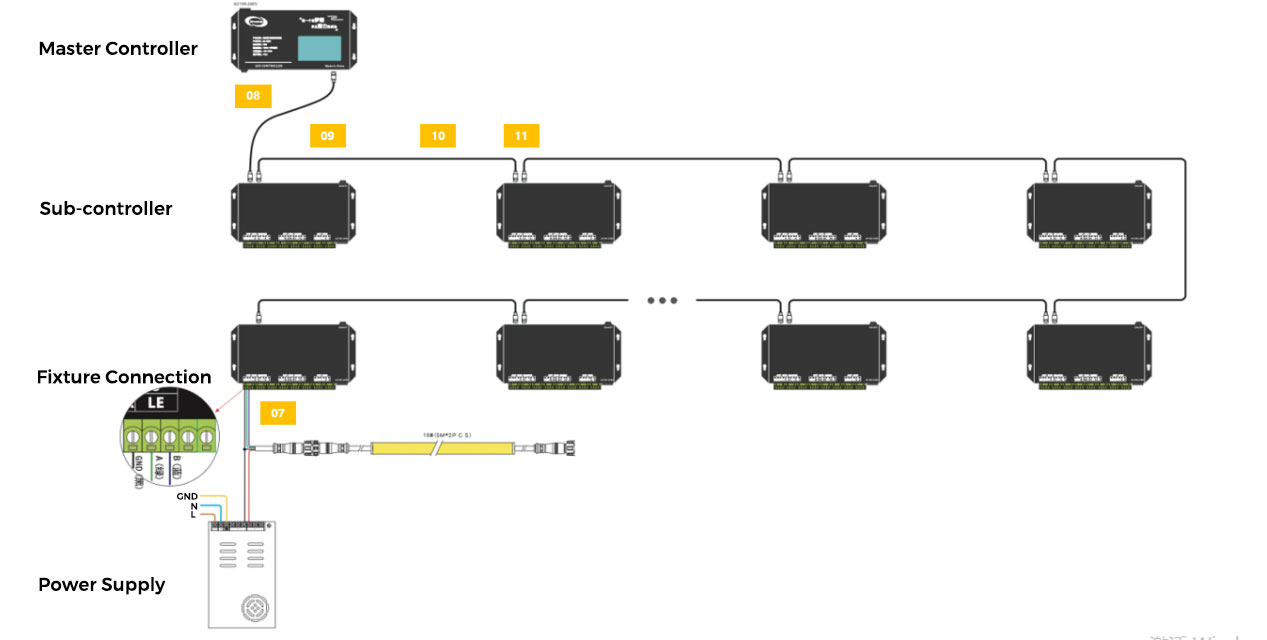
Wiring Schematic Diagram for a Single Standalone Offline Device
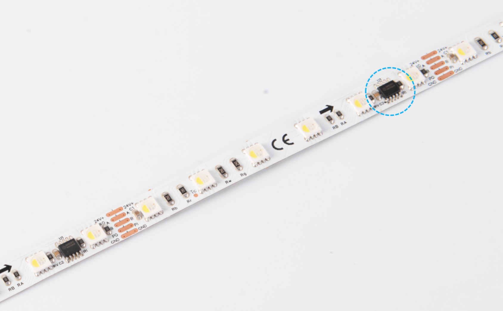
1. DMX512 RGB Neon Strips – Pixel Definition and Segmentation
Definition of Pixel:
A pixel is the smallest independently controllable light-emitting unit on an LED fixture.
Full-color fixtures: Each pixel point is composed of R/G/B (3 channels) or R/G/B/W (4 channels).
Monochrome fixtures: Each pixel point consists of 1 channel or multiple channels of the same color.
Full-color fixtures: Each pixel point is composed of R/G/B (3 channels) or R/G/B/W (4 channels).
Monochrome fixtures: Each pixel point consists of 1 channel or multiple channels of the same color.
The relationship between pixel, point, and segment:
Pixel, point, and segment are commonly interchangeable terms depending on the fixture type.
Point Light Source: A point light source has only one pixel as its color rendering unit, hence the term “point.”
Linear Light: Each fixture consists of multiple segments, with one segment being the smallest color rendering unit, hence the term “segment.”
Point Light Source: A point light source has only one pixel as its color rendering unit, hence the term “point.”
Linear Light: Each fixture consists of multiple segments, with one segment being the smallest color rendering unit, hence the term “segment.”
The significance of pixel display units:
As display units, the more pixels there are, the finer the display resolution:
≥4 segments/meter: enables flowing light effects.
≥8 segments/meter: allows video display effects.
The larger the display unit and unit spacing, the farther the optimal viewing distance.
≥4 segments/meter: enables flowing light effects.
≥8 segments/meter: allows video display effects.
The larger the display unit and unit spacing, the farther the optimal viewing distance.
2. DMX512 RGB Neon Strips – Control IC Models and System Compatibility
The USITT DMX512-1990 is an international standard protocol, compatible with all compliant fixtures. Most ICs on the market support both the DMX512-1990 and its extended versions.
Main Differences – Addressing Protocols:
Different chip manufacturers and models may have variations in the specific implementation of the address writing protocol.
Different chip manufacturers and models may have variations in the specific implementation of the address writing protocol.
3. DMX512 RGB Neon Strips – Cascading Length and Power Supply Considerations
In project applications, the cascading length of RGB neon strips primarily depends on two factors:
Voltage Drop: Excessive length causes brightness inconsistency due to voltage loss.
Controller Output Capacity: Limited by how many pixels a port can control.
Controller Output Capacity: Limited by how many pixels a port can control.
If the controller port's load capacity length exceeds the supply voltage drop limit length, the cascading length should be based on the supply voltage drop limit load capacity length. Conversely, if the port's load capacity length does not meet the requirement, it should be adjusted accordingly.

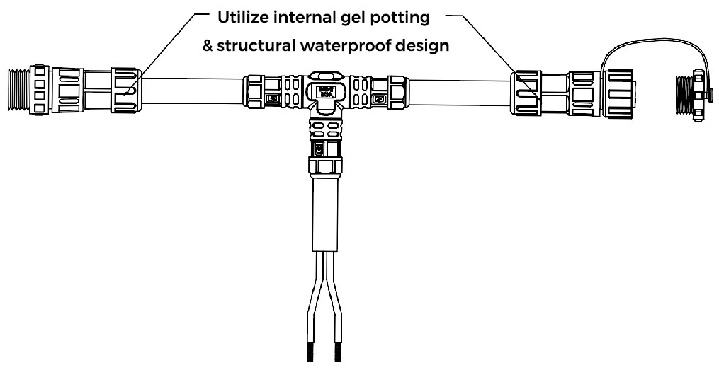
4. DMX512 RGB Neon Strip – Direct Connection, T-Connectors, and Waterproofing
Waterproof Connectors:
Our waterproof male/female connectors utilize dual protection, internal gel potting, and structural waterproof design, and this ensures they meet the IP67 waterproofing standard.
Our waterproof male and female connectors are manufactured using a dual-process approach: after the pins are soldered, they undergo “internal potting compound encapsulation + structural waterproofing design.” This process ensures they meet the IP67 waterproofing standard.
This design demonstrates outstanding reliability and stability in outdoor engineering projects, effectively resisting rainwater, moisture, and dust intrusion, offering long-term stability in complex outdoor environments.
5. Distance Between Sub-controllers and Fixtures & RP Repeater Application
DMX512 Protocol:
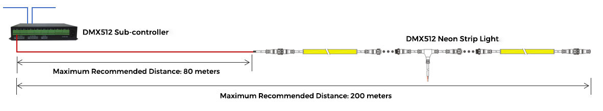
The maximum recommended distance between the controller and the first pixel of the fixture is 80 meters.
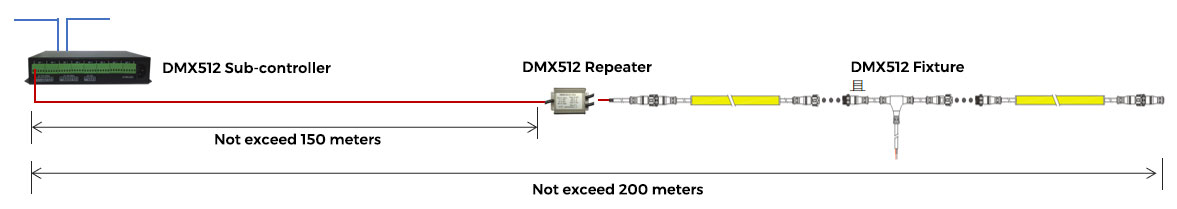
If the distance exceeds this limit, signal attenuation may occur, and a repeater can be used to amplify the signal. The maximum recommended cable length should not exceed 150 meters. The total distance from the first to the last control unit in the DMX signal chain should not exceed 200 meters.
If the distance exceeds this limit, signal attenuation may occur, and a repeater can be used to amplify the signal. The maximum recommended cable length should not exceed 150 meters. The total distance from the first to the last control unit in the DMX signal chain should not exceed 200 meters.
Application of DMX512 neon strip lights directly driven by sub-controllers.
Application of DMX512 repeaters in series with sub-controllers.
6. Wiring Guidelines
6.1 DMX512 System – Signal Wiring Guidelines
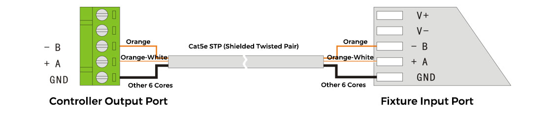
1. For long-distance connections between the controller and fixture, use RS485 cable or Cat5e shielded twisted pair (STP). The optimal wiring configuration is as follows: Orange—B; Orange-White—A; all other wires should be connected to GND (ground).
2. Place a 120Ω termination resistor between A and B at the end of each signal line.
3.Never use two twisted wires simultaneously for signal connections, such as connecting both orange and orange-white wires to either A or B.
6.2 DMX512 Signal Repeater – Wiring Guidelines
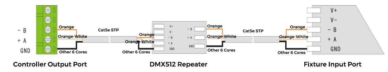
1. For long-distance connections between the controller and fixture, add a DMX repeater before the first pixel, use RS485 cable or Cat5e shielded twisted pair (STP). The optimal wiring configuration is as follows: Orange—B; Orange-White—A; all other wires should be connected to GND (ground).
2. Place a 120Ω termination resistor between A and B at the end of each signal line.
3. Never use two twisted wires simultaneously for signal connections, such as connecting both orange and orange-white wires to either A or B.
Integrated Connection and Disconnection Control Architecture
7. How Many Pixels Can One Offline Sub-Controller Handle?
Standard DMX512-1990 Protocol
Dynamic white light: Each port can support a maximum of 512 pixels, so an 8-port sub-controller can support 512 × 8 = 4,096 pixels.
RGB Color: Each port can support a maximum of 512 ÷ 3 ≈ 170 pixels, so an 8-port sub-controller can control 170 × 8 = 1,360 pixels.
RGBW Color: Each port can support a maximum of 512 ÷ 4 = 128 pixels, so an 8-port sub-controller can control 128 × 8 = 1,024 pixels.
RGB Color: Each port can support a maximum of 512 ÷ 3 ≈ 170 pixels, so an 8-port sub-controller can control 170 × 8 = 1,360 pixels.
RGBW Color: Each port can support a maximum of 512 ÷ 4 = 128 pixels, so an 8-port sub-controller can control 128 × 8 = 1,024 pixels.
Extended DMX512 Protocol:
- Dynamic white light: Each port has a maximum load capacity of 1536 pixels. To ensure smooth video performance, it is recommended not to exceed 900 pixels per port. Therefore, an 8-port controller is recommended to load 900 × 8 = 7200 pixels.
- RGB Color: Each port has a maximum load capacity of 1536 ÷ 3 = 512 pixels. To ensure smooth video performance, it is recommended not to exceed 300 pixels per port. Therefore, an 8-port controller is recommended to load 300 × 8 = 2400 pixels.
- RGBW Color: The maximum load per port is 1536 ÷ 4 = 384 pixels. To ensure smooth video performance, it is recommended that the load does not exceed 225 pixels. Therefore, an 8-port controller is recommended to have a load of 225 × 8 = 1800 pixels.

8. How Many Sub-Controllers Can One Master Controller Manage?
Factors affecting the load capacity of a master controller (offline master controller):
The load capacity of a master controller is not determined by the number of sub-controllers it supports, but by the number of pixels it supports.
Number of pixels supported by the master controller (offline master controller):
Generally, master controllers on the market support around 120,000 pixels. For example, the MR-BF12B supports 150,000 pixels.
Calculation Formula:
No. of Sub-Controllers = Master Pixel Capacity ÷ (Pixels per Port × No. of Ports per Sub-Controller)
Examples:
Examples:
Standard DMX512-1990: 150,000 ÷ (170 × 8) ≈ 111 units
Extended DMX512: 150,000 ÷ (512 × 8) ≈ 37 units
Extended DMX512: 150,000 ÷ (512 × 8) ≈ 37 units
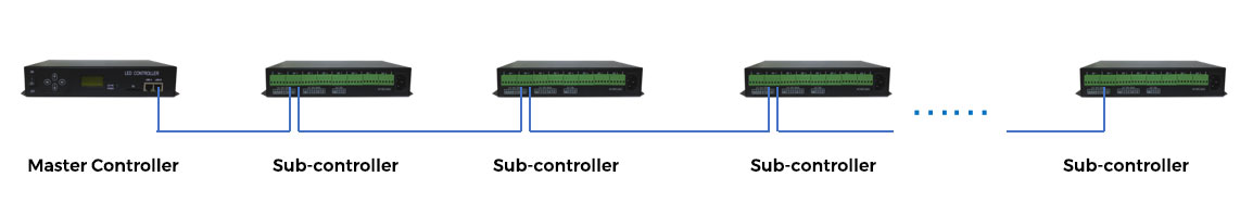
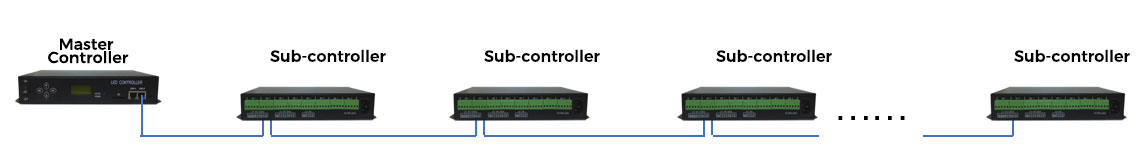
Empirical value for the number of sub-controllers that can be daisy-chained to a master controller
Generally, the number of sub-controllers that can be daisy-chained to a master controller should not exceed 30 units.
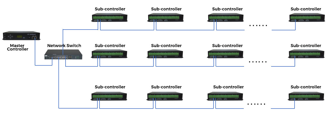
What if there are more than 30 sub-controllers?
A network switch can be added between the master controller and sub-controllers. Each group of 30 sub-controllers can be daisy-chained into one group, and multiple groups of sub-controllers can be divided via the switch.
9. What Cables Are Used Between Controllers? What Is The Cable Length?
Communication data between controller devices:
Communication data is transmitted between controller devices (including master controllers and slave controllers) using the standard UDP network protocol.
Wiring and Connectors:
Cables are typically Category 5e twisted-pair cables, and interfaces use standard RJ-45 network connectors (commonly known as “crystal heads” ).
Cables are typically Category 5e twisted-pair cables, and interfaces use standard RJ-45 network connectors (commonly known as “crystal heads” ).
Cable Length Limitations:
Max distance per Cat5e cable should not exceed 100 meters.
Max distance per Cat5e cable should not exceed 100 meters.
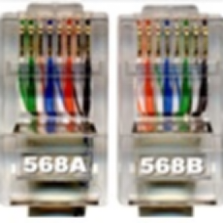
RJ-45 Wiring Standards:
Generally divided into 568A and 568B. Straight-through cables have both ends configured as 568B, while crossover cables have one end as 568A and the other as 568B.
Generally, crossover cables have better interference resistance than straight-through cables.
Generally divided into 568A and 568B. Straight-through cables have both ends configured as 568B, while crossover cables have one end as 568A and the other as 568B.
Generally, crossover cables have better interference resistance than straight-through cables.
10. What If the Network Cable Between Control Devices Exceeds 100 Meters?
Solution: Optical Fiber Transmission
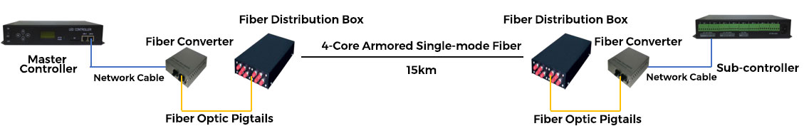
Since the system uses standard network protocols, fiber optic networks can be directly integrated.
Since the system uses standard network protocols, fiber optic networks can be directly integrated.
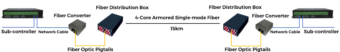
Fiber Types:
Single-mode: transmission distance of up to 15 km
Multi-mode: transmission distance of up to 550 meters.
Single-mode: transmission distance of up to 15 km
Multi-mode: transmission distance of up to 550 meters.
Master to sub-controller via fiber:
Sub-controller to sub-controller via fiber:
11. Network Cable Selection & Wiring Notes
a. Use Cat5e or higher-grade network cables for signal transmission.
b. Regarding network cable (Category 5e twisted pair) wiring sequences.
Network cable connectors use the 568A or 568B wiring sequences:
-
- 568A: Green-white, green, orange-white, blue, blue-white, orange, brown-white, brown
- 568B: Orange-white, orange, green-white, blue, blue-white, green, brown-white, brown
c. For standard protocols, the transmission distance between controllers does not exceed 100 meters.
d. Computers to the controllers: Use the 568B straight-through pinout. Controllers can use either a straight-through cable or a crossover cable (one end 568B, the other end 568A). If the distance between controllers is significant, it is recommended to use a crossover pinout.
Conclusion
COLORS Lighting, the LED linear lighting solutions provider, specialises in the research, development, and manufacturing of high-quality lighting products, which have been certified by all major national markets and are exported to more than 100 countries and regions worldwide.
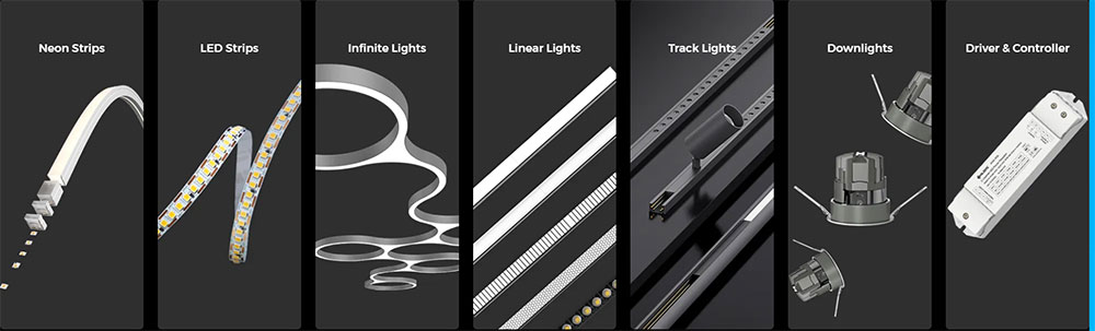
Our product portfolio covers Neon Strips, LED Strips, Infinite Lights, Linear Lights, Track lights, and Downlights. COLORS Lighting provides integrated and professional lighting solutions for residential, hotel, office, commercial, and outdoor spaces.
We have a professional lighting design team, key projects to provide pre-design planning, mid-term selection simulation, post-installation and commissioning of professional support. For key projects, we can cooperate with designers and engineers to deepen the pre-sale product application program. Welcome to contact us and tell us which products you prefer, or let us know what type of lighting solution you need. Let us help your lighting project! COLORS Lighting, Colorful Life!